Re: Jansen 4/TWELVE SPECIAL
Posted: Fri Nov 09, 2018 3:31 pm
My vibrolux is basically a harvard with trem....GrantB wrote:I have always wanted a Harvard!
A forum for Guitarists, by Guitarists
https://www.nzguitars.com/forum/
My vibrolux is basically a harvard with trem....GrantB wrote:I have always wanted a Harvard!
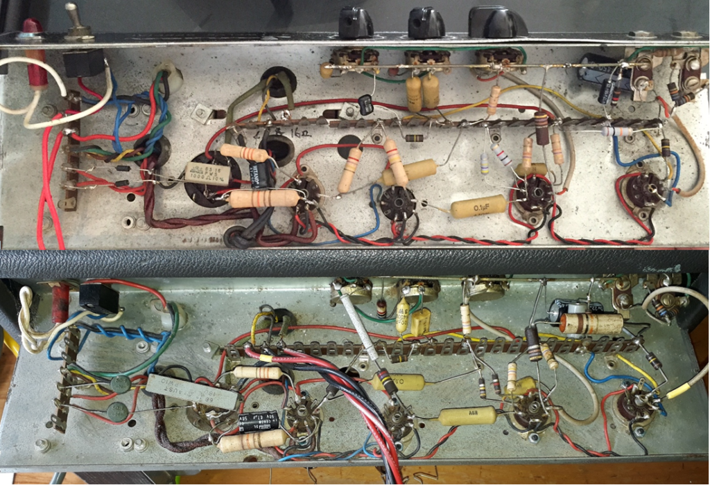
With R7 clarified, the tone controls are actually a bog standard Fender tone stack, but the mid pot is replaced with that fixed resistor. You could put a 25k pot in place of that resistor, even internally, to see if something better emerges.jvpp wrote: C5 - I have chosen a value in between what you suggested, so going with 120pF.
Thanks, will do. Which fixed resistor you are referring to? Confirming C3 is 4.7nF.Optical wrote:With R7 clarified, the tone controls are actually a bog standard Fender tone stack, but the mid pot is replaced with that fixed resistor. You could put a 25k pot in place of that resistor, even internally, to see if something better emerges.jvpp wrote: C5 - I have chosen a value in between what you suggested, so going with 120pF.
Also the C3 4.7nF cap is typically 47nF in a Fender, so check it has been read correctly too.
Anyway, the circuit isnt particularly sensitive to the C5 treble cap value, but you could experiment with the value from 100pF to 1nF. Or model it using the handy Duncan tone stack calculator program
I think we now have a good circuit diagram. I have plenty of photos of its guts and taken chassis measurements, so should be all good to swap our amps back again.Slowy wrote:
One final point: Don't think for a second that I don't miss it!
R7 - the 6k9. It's a strange value which I think would only be explained by the Jansen designer having a pot there, turning it to where they liked it best, then replacing it with a fixed resistor. I'm just suggesting you could use a pot instead of R7 which would provide a mid control and of course the factory setting when in the right place.jvpp wrote: Thanks, will do. Which fixed resistor you are referring to? Confirming C3 is 4.7nF.
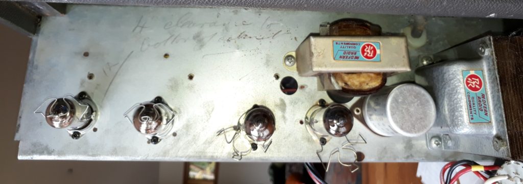
Great, thinking this one might do?sizzlingbadger wrote:Yep, it doesn't mean much though (except its not burnt out), you would normally measure the impedance at 1Khz, usually about 8Kohms to 10Kohms for an EL 84 transformer.
Get the 1760E instead of the 1750Ejvpp wrote:Great, thinking this one might do?sizzlingbadger wrote:Yep, it doesn't mean much though (except its not burnt out), you would normally measure the impedance at 1Khz, usually about 8Kohms to 10Kohms for an EL 84 transformer.
https://www.amplifiedparts.com/products ... der-15w-8k
Only problem is that it is a single secondary. Would prefer the 4 & 16 ohm combinations
It's a "silver mica" type of capacitor. Pricey but potentially more stable alternative to a ceramic cap when small values are wanted e.g 10pF to 10nF.jvpp wrote: something black of which I cannot read the value.
Silver Mica I think it was 250pFOptical wrote:It's a "silver mica" type of capacitor. Pricey but potentially more stable alternative to a ceramic cap when small values are wanted e.g 10pF to 10nF.jvpp wrote: something black of which I cannot read the value.
Maybe look at picking up a cheap LCR meter from ebay (or borrowing one?) to measure the cap values? ...Or just use your ear.