The enclosure below is a 1590XX, larger than intended (the final version will use a 1590BB2 which is the same as the 1590BB but 5mm taller) due to the extra switches and LEDs and pre-drilled from me by the lovely people at Tayda Electronics (https://www.taydaelectronics.com). Because I can't seem to be able to drill holes in a straight line to save myself!
Since the prototype is just a proof of concept build, I didn't worry about the aesthetics as the control layout, especially the switching, aren't true to what I have in mind for the final version.
Below: The drilled enclosure ready to go.

With that said, I'd thought I'd take this opportunity to provide a bit of an update on how things have evolved/progressed since I started this whole prototype process begun and explain a few things in more detail.
Below: A mock-up of the controls. Nothing inside yet however.
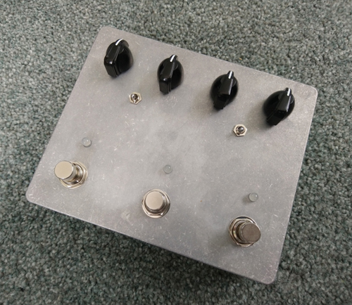
But first, let me explain the controls on the prototype:
Potentiometer Controls (from left to right):
Speed One
The default speed control used to adjust the speed of the oscillation.
Speed Two
The auxiliary speed control used to adjust the speed of the oscillation. Switching between the two speed controls is done via the footswitch on the left.
Intensity
Controls the intensity of the oscillation.
Volume
Control of overall output of the effect.
Toggle Switches (from left to right):
Mode Toggle Switch
Toggles between the Chorus mode that the Uni-Vibe is famous for and lesser used Vibrato mode.
Input Mode Toggle Switch
Toggles between the Vintage and Modern input modes. The Vintage mode provides a warmer, slightly darker tone with a little less output and is the stock circuitry as found in the original. The Modern mode provides a bright tone with more output and clarity.
Status LEDs (from left to right):
Effect Mode LED
Indicates which mode the pedal is in; either Chorus or Vibrato using a bicolour LED. Which colours exactly, I've yet to decide.
LFO LED
Provides visual indication of the speed and intensity of the modulation. Turns off completely when in Cancel mode.
Input Mode/Status LED
Indicates whether the pedal is in bypass mode or the effect is engaged i.e. the LED on or off. Also doubles as an indicator of the Input mode using a bicolour LED. Blue indicates Vintage mode and Red, Modern mode.
Footswitches (from left to right):
Speed Selection
Toggles between the Speed One and Speed Two.
Cancel Mode
Turns the LFO off just like the original so you can still use the pre-amp. Note: The volume control remains active still.
Bypass
Your typical true bypass.
How will these controls differ from the final version you ask? The potentiometer controls will remain exactly the same. The toggle switches will disappear totally as will one of the LEDs and one of the footswitches. All of the switchings will be done via two soft-touch footswitches each with multiple functions assigned to them via a microcontroller. A quick-tap does one thing, a double-tap does something else, and a press-and-hold does yet something else. One footswitch will control the bypass and the Cancel function and the other controls the toggling between the two speed controls, the two effect modes, and the two input modes.
The Input Mode/Status LED will remain the same in terms of functionality but the separate Effect Mode LED will also disappear and instead, its functionality will be incorporated in the LFO LED i.e. still with two separate colours each representing either the Chorus or Vibrato mode while still flashing to represent the speed and intensity of the modulation. But once in Cancel mode, the LED will stop flashing and instead, turn a solid red to indicate the LFO is turned off. The magic of the RGB LED.
So what has changed circuit wise? Remembering this was a straight to PCB design so I hadn't played around with it on a breadboard etc. But in short, a few things.
First of all, the power supply wasn't up to par. While functional, the first issue it caused was the sagging under load. Using the high-side switching to cancel the modulation by killing to power altered its behaviour since the circuit wasn't being loaded down by the current hungry lightbulb; it would operate as intended when the blub was on but not when off.
Secondly, I had yet to include the over-voltage protection that I was intending to use to protect the charge pump (rated to up to 15-volts) so things were getting rather complicated so I made the call to simplify a few things. The power supply now uses an XL6009 DC-DC converter that can handle an input of up to 36-volts. Thus, making the need for any over-voltage protection pretty much redundant. It is also simpler to implement than the LT1054 that I originally intended to use and can pump out higher voltages to boot and much more current. All while using a standard, Boss-style 9-volt DC power supply.
The power filter also needed to be beefed up as it was a bit squelchy otherwise. These changes actually made it closer to the original unit in terms of voltages i.e. 18-volts to the audio section using the exact same power filtering as the original and a hair under 23-volts to the LFO section. A win here I feel; both in terms of simplifying trying while staying true to the source material. One of my aims when setting out on this journey.
Another issue with the LFO LED circuitry itself. There was some minor interaction with biasing that section of the circuit and biasing the bulb for the LDRs. Again, in the name of simplicity, I decided to drop it altogether i.e. the op-amp buffer in the LFOs path and opt for an alternate, much simpler version that does the same thing but without unnecessary complexity or the bothersome interaction. Another win for simplification and staying true to the source material.
The final major change following that same theme (simplification and staying true to the source material), was to the Cancel function. It originally used a high-side mosfet switch that I designed to trickle a small amount of power to the bulb in order to reduce the turn-on time of the bulb and hence the delay time until the modulation kicking it due to the bulb's warm-up time. However, with the simpler LFO LED arrangement now in place, this small amount of power resulted in issues with the functionality of LFO LED again. Whack-A-Mole anyone? So, I reconfigured it to use a low-side mosfet switch instead and to be once again more in line with the functionality of the original unit i.e. shorting the signal from the LFO to ground rather than killing to power to the bulb. This means there is a slight delay if using that option (a quirk shared by the original) but the increase in power to the LFO section helped and it is dependant on the speed and intensity settings that control the amount of current flowing through the bulb.
I also made a change to expand the speed range available to the LFO by tweaking and experimenting a little with three resistor values thanks again to another mod suggested by J.C. Maillet (http://www.lynx.net/~jc/pedalsUnivibe.html). The last minor change was to the use of multi-turn trimpots instead of their single-turn cousins. Since the biasing of the bulb is SO vitally important to getting the Uni-Vibe to sound right, these allow for much finer adjustment to really dial in that sweet spot.
Don't worry; it still sounds fantastic!
Below: The current stage of play.

For the audio section of the circuit, nothing changed. Oh; I did get the correct SMD 68k resistor that I had previously forgotten to order.
Below: Before.

Below: After.

Any questions and comments, as always, are most welcome.
~ Blake.