Below:Top-mounted jacks with a flush DC power jack.
And lastly, some low-hanging fruit in terms of assembly. The switching board. I really like these particular soft-touch switches but might have to change to a slightly different version due to the fact that I have only been able to find them from one supplier and the cost of shipping is quite high compared to all of the others that I use.
Since the two PCBs will be sandwiched between a series of header pins in each of the corners, I temporarily tacked on a bunch of wires so I can access the bottom of the PCBs just in case anything needs troubleshooting.
I could have given Mister Shake Hands Man from Banzai a run for his money with the amount my hands were shaking as I was approaching the moment of truth of having to power it up for the first time.
I was more worried about if I had made a mistake in the actual PCB design than anything else. I could troubleshoot things like incorrect part place, dodgy solder joints etc, and I could potentially bodge something, if need be, if there was a flaw in the actual PCB(s) depending on what it was.
So it was a high relief when I powered it up for the first time everything and the LFO started LFOing immediately, the all of the switching controlled by the microcontroller triggered all of the relays and LEDs as intended. The LFO responded to both Speed controls as well as the Intensity and Volume controls. And the bypass worked.
But just as I thought I'd cracked it, unfortunately, the Cancel function wasn't working as intended. It killed the LFO as it should but the strength of the audio signal was extremely low for some reason when it was engaged. After breaking out the Audio Probe, I discovered three different locations in phase phase-shifting section of the circuit where I had been a little too stingy when applying the solder paste.
Once those were addressed, I was extremely happy to say that everything is working as it should.
The moral of the story is, that while a little bit of solder paste does indeed go a long way, you still need enough in order to create a solid connection.
FuzzMonkey wrote: ↑Fri Oct 13, 2023 3:27 pm
Testing time.
Since the two PCBs will be sandwiched between a series of header pins in each of the corners, I temporarily tacked on a bunch of wires so I can access the bottom of the PCBs just in case anything needs troubleshooting.
I could have given Mister Shake Hands Man from Banzai a run for his money with the amount my hands were shaking as I was approaching the moment of truth of having to power it up for the first time.
I was more worried about if I had made a mistake in the actual PCB design than anything else. I could troubleshoot things like incorrect part place, dodgy solder joints etc, and I could potentially bodge something, if need be, if there was a flaw in the actual PCB(s) depending on what it was.
So it was a high relief when I powered it up for the first time everything and the LFO started LFOing immediately, the all of the switching controlled by the microcontroller triggered all of the relays and LEDs as intended. The LFO responded to both Speed controls as well as the Intensity and Volume controls. And the bypass worked.
But just as I thought I'd cracked it, unfortunately, the Cancel function wasn't working as intended. It killed the LFO as it should but the strength of the audio signal was extremely low for some reason when it was engaged. After breaking out the Audio Probe, I discovered three different locations in phase phase-shifting section of the circuit where I had been a little too stingy when applying the solder paste.
Once those were addressed, I was extremely happy to say that everything is working as it should.
The moral of the story is, that while a little bit of solder paste does indeed go a long way, you still need enough in order to create a solid connection.
I forgot a step after my last update. And that is, of course, the final assembly. Of the PCBs at least.
After all the testing and troubleshooting tasks were done, it was time to remove all that temporary wiring and install the header pins and ribbon connectors.
Below:The LFO side.
Below:The Audio side.
Below:The footswitches.
Below:A closer look at the LFO side.
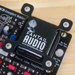
Below:The Input/Output/Power board.
There are four sets of header pins, one in each corner that hold the two PCBs together. Making a PCB Sandwich if you will.
Below:The PCB sandwich.
These header pins serve two purposes. One is to provide space between the two boards so none of the through-hole components can touch and create a short or blow anything up. And two, carry things like power, signals from the microcontroller, ground connections etc between the two PCBs.
The all-important lightshield prevents any external light pollution from getting to LDRs and messing with their response.
Below:Where the magic happens; the bulb and LDRs.
Below:Buliding the walls of the lightshield.
Below:Installing the roof.
Next up is the actual final calibration of the bulb.
jeremyb wrote: ↑Thu Oct 19, 2023 6:45 pm
Looks great! Interested to know about the jumper pins above the ribbon cable?
Those are to program the microcontroller. I have a Tiny AVR Programmer (https://www.sparkfun.com/products/11801) that I use to program ATTiny microcontrollers. It allows me to solder in the microcontroller, in this case, I am using an ATTiny84, and then program it by using those header pins connected via six jumper wires attached to the Tiny AVR Programmer. Makes it a lot easier to re-program if need be.
Cdog wrote: ↑Thu Oct 19, 2023 8:46 pm
This is a very cool project
Thanks Corey.
AiRdAd wrote: ↑Fri Oct 20, 2023 6:05 am
Wow - just amazing!!!!